The safety of a vehicle and its passengers can be improved by properly
designing and selecting the material for vehicle bodies. The vehicle body
structure is subjected to static and dynamic service loads during the life
cycle. It also has to maintain its integrity and provide adequate protection in
survivable crashes. At present there are two designs of vehicle body
constructions:
1. Body over frame structure and
2. Unibody structure.
1. Body over frame
structure


2. Unibody structure


- This frame is used now a day in most of the cars. There is no frame and all the assembly units are attached to the body.
- All the functions of the frame carried out by the body itself. Only disadvantage is In this type of chassis the ladder frame is absent and the body itself act as the frame.
- It supports all the systems in a vehicle such as the Engine, Transmission system, Steering system,Suspension system.
- Deformable yet stiff front structure with crumple zones to absorb the crash kinetic energy from frontal collisions.
- Deformable rear structure to safeguard rear passenger compartment and protect the fuel tank.
- Properly designed side structures and doors to minimize intrusion in side impact and prevent doors from opening due to crash loads.
- Strong roof structure for rollover protection.
- Properly designed restraint systems with working in harmony with the vehicle structure.
- Accommodate various chassis designs for different power train locations and drive train configurations.
1. Desired dummy performance:

Dummy is a physical model representing humans inside a car. To model a car for safety, it should be modeled for proper crash energy management. Crash test dummies are the key as they are used as replica for human in a crash test. Dummies are made of materials that
imitate human physiology. Though dummies of different sizes are used, dummy weighing 172 lbs (78 kg) and standing at 69 inches (5 ft. 9 inches or 1.75 m) tall is the most frequently used in testing.

As the human beings are to be safeguarded, the interaction of the human beings with the restraint system during a crash has to be studied first. The dummy's job is to simulate a
human being during a crash, while collecting data that would not be possible to collect from a human occupant. Each complex dummy includes 25 to 40 sensors to record the forces on various parts of the body.This branch of study is widely known as bio-mechanics.
Accelerometers: Measure the acceleration in a particular direction. This data can be used to determine the probability of injury. Inside the dummy's head, there is an accelerometer that measures the acceleration in all three directions (fore-aft, up-down, left-right). There are also accelerometers in the other parts of the body.
Load Sensors: Inside the dummy are load sensors that measure the amount of force on different body parts during a crash. The maximum load in the bone can be used to determine the probability of it breaking.
Movement Sensors: These sensors are used in the dummy's chest. They measure how much the chest deflects during a crash. Before the crash test dummies are placed in the vehicle, researchers apply different colors of paint to the parts of the dummies' bodies most likely to hit during a crash. The paint marks in the car will indicate which part of the body got collided with vehicle inside the cabin. This information helps researchers develop improvements to prevent that type of injury in future crashes.
2. Stiff cage structural concept:
imitate human physiology. Though dummies of different sizes are used, dummy weighing 172 lbs (78 kg) and standing at 69 inches (5 ft. 9 inches or 1.75 m) tall is the most frequently used in testing.
As the human beings are to be safeguarded, the interaction of the human beings with the restraint system during a crash has to be studied first. The dummy's job is to simulate a
human being during a crash, while collecting data that would not be possible to collect from a human occupant. Each complex dummy includes 25 to 40 sensors to record the forces on various parts of the body.This branch of study is widely known as bio-mechanics.
Accelerometers: Measure the acceleration in a particular direction. This data can be used to determine the probability of injury. Inside the dummy's head, there is an accelerometer that measures the acceleration in all three directions (fore-aft, up-down, left-right). There are also accelerometers in the other parts of the body.
Load Sensors: Inside the dummy are load sensors that measure the amount of force on different body parts during a crash. The maximum load in the bone can be used to determine the probability of it breaking.
Movement Sensors: These sensors are used in the dummy's chest. They measure how much the chest deflects during a crash. Before the crash test dummies are placed in the vehicle, researchers apply different colors of paint to the parts of the dummies' bodies most likely to hit during a crash. The paint marks in the car will indicate which part of the body got collided with vehicle inside the cabin. This information helps researchers develop improvements to prevent that type of injury in future crashes.
2. Stiff cage structural concept:

Stiff cage is the passenger compartment structure which provides protection for the passengers in all modes of survivable collisions. The necessary features of a good stiff cage structure are:
- Sufficient peak load capacity to support the energy absorbing members in front of it
- High crash energy absorption.
- The stiff cage structure should withstand all the extreme loads and the severe deformation.
3. Controlled progressive crush and deformation with limited intrusion:

To make the impact of crash less, the crush event has to be controlled and the deformation should be made such that the intrusion of other components into the passenger compartment is less. Axial mode of crush is preferred to bending mode of crush as bending mode has lower energy content. To achieve this objective three different crush zones are identified:
Soft front zone: Reduces the aggressively of crash in pedestrian / vehicle and vehicle / vehicle collisions
Primary crush zone: It consists of the main energy absorbing structure before the power train. It is characterized by a relatively uniform progressive structural collapse.
Secondary crush zone:Lies between the primary zone and passenger compartment and sometimes extends into the passenger compartment up to firewall. It provides a stable platform for the primary zone and transfers the load to the occupant compartment as efficiently as possible.
4. Weight efficient energy absorbing structures:
The architecture of the structural frame (structural topology) design depends on the ability to design the primary crush zone for bending, folding, mixed folding and bending. For a given vehicle package different topologies have to be studied for the same crush energy absorption.
The steps followed are:
- Create a simple model of vehicle front-end system
- Determine the design loads of structural members
Basis of body design for safety
- The design of vehicle body for optimum characteristics should be based on basic energy relationship.
- The kinetic energy of a vehicle destroyed during a collision is absorbed by the workdone on materials by elastic deformation.
Energy Equations
The application of the conservation of energy principle provides a powerful tool for problem solving. Newton's laws are used for the solution of many standard problems, but often there are methods using energy, which are more straightforward. For example, the solution for the impact velocity of a falling object is much easier by energy methods. The basic reason for the advantage of the energy approach is that just the beginning and ending energies need to be considered; intermediate processes do not need to be examined in detail since conservation of energy guarantees that the final energy of the system is the same as the initial energy. The work energy principle is also a useful approach to the use of conservation of energy in mechanics problem solving. It is particularly useful in cases where an object is brought to rest as in a car crash or the normal stopping of an automobile.
Kinetic energy is energy of motion. Objects that are moving, such as a roller coaster, have kinetic energy (KE). If a car crashes into a wall at 5 mph, it shouldn't do much damage to the car. But if it hits the wall at 40 mph, the car will most likely be totalled. Kinetic energy is similar to potential energy. The more the object weighs, and the faster it is moving, the more kinetic energy it has.
The formula for KE is: KE = ½(m*v2) where m is the mass and v is the velocity.
One of the interesting things about kinetic energy is that it increases with the velocity squared. This means that if a car is going twice as fast, it has four times the energy. You may have noticed that your car accelerates much faster from 0 mph to 20 mph than it does from 40mph to 60 mph. Let's compare how much kinetic energy is required at each of these speeds. At first glance, you might say that in each case, the car is increasing its speed by 20 mph, and so the energy required for each increase must be the same. But this is not so. We can calculate the kinetic energy required to go from 0 mph to 20 mph by calculating the KE at 20 mph and then subtracting the KE at 0 mph from that number. In this case, it would be ½/*m*202 - ½*m*02.
Because the second part of the equation is 0, the KE = ½*m*202, or 200 m. For the car going from 40 mph to 60 mph, the KE = ½*m*602 - ½*m*402; so KE = 1,800 m - 800 m, or 1000m.
Comparing the two results, we can see that it takes a KE of 1,000 m to go from 40 mph to 60mph, whereas it only takes 200 m to go from 0 mph to 20 mph.
There are a lot of other factors involved in determining a car's acceleration, such as aerodynamic drag, which also increases with the velocity squared. Gear ratios determine how much of the engine's power is available at a particular speed, and traction is sometimes a limiting factor. So it's a lot more complicated than just doing a kinetic energy calculation, but that calculation does help to explain the difference in acceleration times.
F=ma (Newton's 2nd law)
F-force,
m-mass, and
a-acceleration.
This can be rewritten more generally as F=(dp/dt) where p is momentum and dp/dt implies a change in momentum with respect to a change in time. Momentum, p, however, is related to kinetic energy, KE, by the equation
KE=p2/2m.
So a change in momentum corresponds to a change in kinetic energy
The kinetic energy of a vehicle destroyed during a collision can be expressed as
K.E = ( m - Nm ) V2 / 2
m = total mass of vehicle
Nm = moveable mass(passenger or load)
V = Velocity
Engine position:

Front engine
The large mass of an engine at the front of the car gives the driver protection in the event of a head on collision.
In addition the cornering ability of a vehicle is normally better if the weight is concentrated at the front.
Disadvantages
- First, braking ability is somewhat diminished. Diminished braking occurs because weight transfers forward under braking, leaving relatively little weight remaining over the rear wheels during braking and thus, limiting the ability of the rear tires to contribute the braking task.
- Accelerative ability is limited somewhat by the relative lack of static weight over the rear tires when, the weight of the vehicle shifts rearward upon acceleration.
Rear engine
- It increases the load on the rear driving wheels, giving them better grip of the road. Most rear-engine layouts have been confined to comparatively small cars, because the heavy engine at the rear has an adverse effect on the ‘handling’ of the car by making it ‘tail-heavy’.
- Rear-engine automobiles tend to demonstrate exceptional braking ability due to a greater amount of weight from the engine remaining over the rear tires during braking. Thus, all four tires are heavily involved during braking instead of just the front tires. Acceleration is also enhanced, as the rearward transfer of weight and the engine weight combine to put maximum downward force on the rear tires (the tires responsible for acceleration in this configuration) resulting in a larger rear tire contact patch that enhances accelerative traction.
- Mid- and rear-engine vehicles will benefit the driver by offering shorter potential stopping distances.
Disadvantage
- Rear-engine vehicle’s tendency to oversteer due to greater weight resident in the rear of the vehicle that results in greater momentum. Recall that oversteer (rear wheel) skids occur when the rear tires lose traction before the front tires, resulting in the rear of the car sliding out sideways or "fishtailing". As oversteer skids are less easily corrected than understeer (front wheel) skids.
Central or mid-engine
- These engine situations generally apply to sports cars because the engine sitting gives a load distribution that achieves both good handling and maximum traction from the driving wheels.
- The mid-engine vehicle is usually associated with high performance automobiles for several reasons. First, the static weight distribution tends to be close to the optimal 50/50 ratio, with the bias being slightly rearward, resulting in superior balance and handling characteristics.
Crumple zone

It was an inventor Bela Barenyi who pioneered the idea that passengers were safer in a vehicle that was designed to easily absorb the energy from an impact and keep that energy away from the people inside the cabin. Barenyi devised a system of placing the car's components in a certain configuration that kept the kinetic energy in the event of a crash away from a bubble protecting the car's occupants. Mercedes obtained patent from Barenyi's invention way back in 1952 and the technology was first introduced into production cars in 1959 in the Mercedes-Benz 220, 220 S and 220 SE models.
Early designs of car bodies were designed to be rigid without much regard for what happened to the car and its occupants in a crash. The laws of physics dictate that if you are driving at 50 mph, and a crash causes the car to stop immediately, passengers will continue moving at 50 mph. The results can be fatal.
The Science Behind Crumple Zones
Isaac Newton's first law of physics says that an object in motion will stay in motion with the same amount of speed and in the same direction unless intervened by an unbalanced force.
And that's exactly what happens with an automobile accident. Passengers continue to move unless stopped by a seat, dashboard, etc. Internal organs continue to move even if the body stops, causing severe injuries.
Newton's second law states that force equals the mass multiplied by acceleration. So, in an automobile accident, the force of the automobile and its occupants decreases if the time required by the vehicle to stop increases.
Function:
Basically, crumple zones work according to Newton's two laws. Placed at the front and rear of the vehicle, they absorb the impact of a head-on collision and help to delay collision impact.Crumple zones work by managing crash energy, absorbing it within the outer sections of the vehicle, rather than being directly transmitted to the occupants, while also preventing intrusion into or deformation of the passenger cabin. This better protects car occupants against injury. This is achieved by controlled weakening of sacrificial outer parts of the car, while strengthening and increasing the rigidity of the inner part of the body of the car, making the passenger cabin into a 'safety cell', by using more reinforcing beam sand higher strength steels.
Instead of very rigid vehicles colliding causing a high likelihood of human casualties, crumple zones take the hit, increasing the time before the vehicle comes to a stop.
Crumple zones accomplish two safety goals.
i) They reduce the initial force of the crash, and
ii) They redistribute the force before it reaches the vehicle's occupants.
The forces that is experienced in an emergency stop are much greater than when the vehicle is gradually slowed down for a stoplight. In a collision, slowing down the deceleration by even a few tenths of a second can create a drastic reduction in the force involved. Force is a simple equation:
Force = mass * acceleration

Volvo introduced the side crumple zone, with the introduction of the SIPS (Side Impact Protection System) in the early 1990s.


Seat belts also absorb energy by being designed to stretch during an impact, so that there is less speed differential between the passenger's body and their vehicle interior. In short: A passenger whose body is decelerated more slowly due to the crumple zone (and other devices) over a longer time, survives much more often than a passenger whose body indirectly impacts a hard, undamaged metal car body which has come to a halt nearly instantaneously. The final impact after a passenger's body hits the car interior, airbag or seat belts, is that of the internal organs hitting the ribcage or skull. The force of this impact is the mechanism through which car crashes cause disabling or life threatening injury. The sequence of energy is dissipating and speed reducing technologies - crumple zone - seat belt - airbags - padded interior, are designed to work together as system, to reduce the force of this final impact.
A common misconception about crumple zones is that they reduce safety by allowing the vehicle's body to collapse, crushing the occupants. In fact, crumple zones are typically located in front and behind of the main body (though side impact absorption systems are starting to be introduced), of the car (which forms a rigid 'safety cell'), compacting within the space of the engine compartment or boot/trunk. The marked improvement over the past two decades in high speed crash test results and real-life accidents also belies any such fears. Modern vehicles using what are commonly termed 'crumple zones' provide far superior protection for their occupants in severe tests than older models, or SUVs that use a separate chassis frame and have no crumple zones.
A common misconception about crumple zones is that they reduce safety by allowing the vehicle's body to collapse, crushing the occupants. In fact, crumple zones are typically located in front and behind of the main body (though side impact absorption systems are starting to be introduced), of the car (which forms a rigid 'safety cell'), compacting within the space of the engine compartment or boot/trunk. The marked improvement over the past two decades in high speed crash test results and real-life accidents also belies any such fears. Modern vehicles using what are commonly termed 'crumple zones' provide far superior protection for their occupants in severe tests than older models, or SUVs that use a separate chassis frame and have no crumple zones.
Collapse Modes for Absorption of the kinetic energy of the vehicle
- Axial
- Bending


Sandwich construction:
The vehicle has to be designed with minimum weight in order to maximize fuel efficiency
and acceleration performance. One way of improvement would be to make the vehicles
lighter by using composite based structures.
Properties of sandwich structures
A sandwich structure represents a special form of a layered structure that consists of
- Two facings, which are relatively thin and of high strength,
- A core is enclosed which is relatively thick and light and which has adequate stiffness in a direction normal to the faces of the panel.
Sandwich composite structures are efficient load carrying materials and are identified as an interesting alternative to traditional construction materials because of their high stiffness to weight ratios. The flexibility of composite sandwich construction allows innovative structural developments from this material.


Assembled composite sandwich (A), and its constituent face sheets or skins (B) and honeycomb core (C)
- The facings may be steel, aluminium, wood, fibre-reinforced plastic or even concrete.
- The core may be made of cork, balsa wood, rubber, paper, solid plastic material (polyethylene), rigid foam material (polyurethane, polystyrene, phenolic foam), mineral wool slabs or from honeycombs of metal or even paper.

a)panel with a polyurethane or polystyrene core
b)panel with a metal or paper honeycomb core
c)panel with a mineral wool core
The principle of
sandwich construction is that bending loads are carried by the skins, while the
core transmits shear load. They enable large gains in structural efficiency,
since the thickness (and hence flexural rigidity)of panels can be increased
without significant weight penalty.


where, Es = modulus of the skin material,
Ρs = density of the skin material,
b = width of the section,
t = thickness of the skins and
d = distance between the skins.
Steel–polymer–steel and aluminum–polymer–aluminum are two commercially available sandwich materials developed for body structures as well as for body panels.Sandwich panels with carbon fiber reinforced polymer in the skins and a polymer foam core can provide much higher weight saving opportunity for body applications.
Glass-fiber polyurethane foam core construction

Sandwich sheets are characterized by a skin to core thickness ratio. If this ratio is low, enables a high bending stiffness at low weight. If this ratio is high, core thickness sufficient to convert the vibrations into frictional heat.
 |
| woven wire mesh core |
Glass-fiber polyurethane foam core construction
Glass-fibre mat is preformed and wrapped around the foam core before being placed into the low pressure injection tool. To ensure accurate location, the glass mat is retained in the part line of the tool. Polyester resin is then injected into the tool which impregnates the glass fibre and completes the sandwich construction.
With a 40 per cent by weight ratio of glass reinforcement to resin, the resultant assembly weighs approximately 30 per cent less than an equivalent steel structure with energy absorbing characteristics of the panels shown to be 87 per cent higher than for standard steel parts.
Skin to core thickness ratio Sandwich sheets are characterized by a skin to core thickness ratio. If this ratio is low, enables a high bending stiffness at low weight. If this ratio is high, core thickness sufficient to convert the vibrations into frictional heat.
- This material type is only viable for components that are assembled into the body after the painting process.
- This material is not weld able and must be assembled by a cold joining process of either adhesive bonding or mechanical fastening.
Applications:
Roof panels, body panels, hardtops, body floors.
Active safety:
It refers to devices and systems that help keep a car under control and prevent an accident. These devices are usually automated to help compensate for human error -- the single biggest cause of car accidents.
1. Anti-lock brakes prevent the wheels from locking up when the driver brakes, enabling the
driver to steer while braking.
2. Traction control systems prevent the wheels from slipping while the car is accelerating.
3. Electronic stability control keeps the car under control and on the road.
4. Adaptive cruise control-adjust the vehicle speed based on the traffic environment
5. Tyre pressure monitoring system monitors the air pressure inside the pneumatic tyres
6. Lane departure warning warn the driver when the vehicle is moving out of its lane
7. Night vision system extend the perception of the driver beyond the limited reach of
headlights
8. Blind spot detection system detects other vehicles located to the driver's side and rear
9. Driver monitoring system is to monitor the driver's attentiveness while driving
10. Road sign recognition system notify and warns the driver of enforced restrictions on the
8. Blind spot detection system detects other vehicles located to the driver's side and rear
9. Driver monitoring system is to monitor the driver's attentiveness while driving
10. Road sign recognition system notify and warns the driver of enforced restrictions on the
road
Passive safety:
It refers to systems in the car that protect the driver and passengers from injury if an accident does occur.
Passive safety:
It refers to systems in the car that protect the driver and passengers from injury if an accident does occur.
- Air bags (front, window, side, knee, front to rear passengers) - prevent the collision
of the body, respectively individual body parts of the steering wheel, instrument panel and other interior parts of the vehicle absorb shock and reduce the risk of injury - Seat belts hold passengers in place so that they aren't thrown forward or ejected from the car.
- Rollover bars protect the car's occupants from injury if the vehicle rolls over during an accident.
- Passenger safety cell
- Crumple zones – reducing the impact of the collision while designing their body structure.
- Whiplash protection- backrest prevent the driver and passengers from getting whiplash during a rear-end collision.
- Child safety system-specifically designed seats that protect children from injury or death during collision.
- Belt bags
- Collapsible steering column – in case of an accident it reduces the driver’s risk of hitting the steering wheel.
- FPS (Fire Protection System Safety) – a system which blocks the supply of electricity and fuel in case of an accident, to avoid the risk of fire.
Crashworthiness is generally defined as the ability of a structure to resist the effects of an impact with another object. In automotive industry, it aims to ensure the vehicle structural integrity and its ability to absorb crash energy with minimal diminution of survival space.
Classification of crashworthiness criteria
1) Injury-based metrics
From a biomechanics point of view, occupant's responses to a crash can be measured by such indices as head injury criteria (HIC), chest acceleration, chest deflection and femur loadsunder impact. These indices are affected by the vehicle crash pulse (CP), the magnitude of intrusion (Intr) into the occupant compartment, restraint system, and vehicle interiors.
2) Energy-based metrics
The crashworthy structures are expected to absorb as much energy as possible so as to reduce the kinetic energy transmitting to the occupants. Hence, the amount of energy absorption (EA) has been drawn exhaustive attention by researchers.

where F(s) is the instantaneous impact force at the crash distance s and d the total crash displacement concerned for measuring the energy absorption.
Formulations of crashworthiness criteria in optimization
1. Analytical functions
2. Direct coupling with finite element analysis
3. Surrogate modeling
Crash test

A crash test for vehicle safety is a type of destructive testing undertaken to ensure that standards for safe design with regards to crash compatibility and crash worthiness are followed for different transportation modes. A thorough crash-testing program is critical for the car makers and has contributed significantly to the improving safety of cars.
According to the New Car Assessment Program (NCAP) of National Highway Traffic Safety Administration (NHTSA) cars made for model year 1997 and after must pass both the tests frontal crash testing and side impact crash testing.
Regulatory Requirements
As per the Indian government’s latest safety norms (applicable to all new models since October 2017, and to all models on sale from October 2019), to be eligible for sale, a car must meet front offset and side impact crash requirements. The Indian government’s front offset test is conducted at 56kph which, though lower than the Global NCAP’s front offset crash test speed, is in line with the United Nations’ Regulation 94 for front impact protection.

These scores are primarily derived from readings of the crash-test dummies but additional points may be awarded for the presence of certain safety features. Additionally, Global NCAP mandates a driver’s side airbag as the minimum requirement to qualify for a one star rating. This should explain why non-airbag versions of the Tata Zest and Volkswagen Polo received zero stars, while airbag-equipped versions tested later were rated 4-star cars.
The 17-point Adult Occupant Protection score takes into account driver injury readings from four body regions – head and neck; chest; knee, femur and pelvis, and leg and foot. An additional point is given to cars with a seatbelt reminder, four-channel ABS and some form of side-impact protection, tested by a relevant authority.
The primary basis for the 49- point Child Occupant Protection score is readings from the 18- month-old and 3-year-old-sized dummies placed in manufacturer recommended child seats. Additional points are given for child restraint system markings, provision of three point seat belts, Isofix, etc.

Types of crash/roll over tests
1. Frontal impact test

At 35 mph (56 kmph), the car runs straight into a solid concrete barrier. This is equivalent to a car moving at 35 mph hitting another car of comparable weight moving at 35 mph. The kinetic energy involved in the frontal crash test depends on the speed and weight of the test vehicle.


In the offset crash test the vehicle is travels at 64kph (40mph) and collides with a crushable aluminum barrier, which makes the forces in the test similar to those involved in a frontal offset crash between two vehicles of the same weight.
The vehicle structure affects the outcome of an offset frontal crash in two main ways:


Regulatory Requirements
As per the Indian government’s latest safety norms (applicable to all new models since October 2017, and to all models on sale from October 2019), to be eligible for sale, a car must meet front offset and side impact crash requirements. The Indian government’s front offset test is conducted at 56kph which, though lower than the Global NCAP’s front offset crash test speed, is in line with the United Nations’ Regulation 94 for front impact protection.
These scores are primarily derived from readings of the crash-test dummies but additional points may be awarded for the presence of certain safety features. Additionally, Global NCAP mandates a driver’s side airbag as the minimum requirement to qualify for a one star rating. This should explain why non-airbag versions of the Tata Zest and Volkswagen Polo received zero stars, while airbag-equipped versions tested later were rated 4-star cars.
The 17-point Adult Occupant Protection score takes into account driver injury readings from four body regions – head and neck; chest; knee, femur and pelvis, and leg and foot. An additional point is given to cars with a seatbelt reminder, four-channel ABS and some form of side-impact protection, tested by a relevant authority.
The primary basis for the 49- point Child Occupant Protection score is readings from the 18- month-old and 3-year-old-sized dummies placed in manufacturer recommended child seats. Additional points are given for child restraint system markings, provision of three point seat belts, Isofix, etc.
- A crash laboratory with an advanced high-tech crash barrier.
- An outdoor test track that accommodates research for different weather conditions.
- Highly advanced crash simulator .
- Lighting system, which can provide up to 750,000 watts of illumination without glare to film tests in slow motion. The resulting pictures must be clear and dramatic.
- The crash dummies of different sizes industry standard that complied with government
regulations. - Barrier design:The concrete barrier dimensions depend of the type of test.The barrier is made of a steel plate with a thickness of 38.1 mm, it’s 1000 mm wide, and has a
 radius on the right edge. The radius has a 115 degrees arc, the height of the barrier is 1524 mm from the floor and the mass is 145,150 kg.
 - Test vehicle preparation:In the test facility all vehicles that are prior for tests are inspected for missing parts, damaged areas and repaired areas. All fluids in the vehicles are removed, battery acid, air conditioning agent, cooling agent and gasoline/diesel.
- The vehicle is attached to the propulsion system via chains fitted underneath the
front of the vehicle. Sensors and cameras are added to the interior of the vehicle
along with the crash test dummy occupants.
1. Frontal impact test
At 35 mph (56 kmph), the car runs straight into a solid concrete barrier. This is equivalent to a car moving at 35 mph hitting another car of comparable weight moving at 35 mph. The kinetic energy involved in the frontal crash test depends on the speed and weight of the test vehicle.
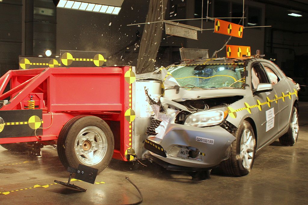
2. Side impact test
In the side test a sled (of about 1,368-kg) with a deformable "bumper" runs into the side of the test vehicle at around 31mph. The test simulates a car that is crossing an intersection being sides wiped by a car running a red light.
Side impacts can be of two types: - perpendicular impact and angled impact The protection of occupants in side impacts is more important as the space between the car’s body and the occupant is much less than with the front and rear.

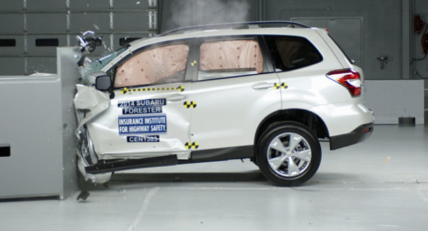
3.Frontal Offset Crash Testing
In offset tests, only one side of a vehicle's front end, not the full width, hits the barrier so that a smaller area of the structure, about 40% of the width of the front of the vehicle on the driver's side must manage the crash energy.
In the offset crash test the vehicle is travels at 64kph (40mph) and collides with a crushable aluminum barrier, which makes the forces in the test similar to those involved in a frontal offset crash between two vehicles of the same weight.
The vehicle structure affects the outcome of an offset frontal crash in two main ways:
1. Absorption and dissipation of crash energy and
2. Integrity of the passenger compartment.
4. Rollover test
A rollover test verifies the car’s ability to support itself, especially from the pillars supporting the roof, during a dynamic impact. Roadside hardware crash tests ensure that crash barriers and crash cushions protect the passengers of the vehicle from roadside hazards. This kind of crash test also makes sure that some appurtenances such as sign posts, guard rails, light poles may not serve as a hazard to vehicle occupants.
Crash test analysis


High Speed Photography, Image analysis
One of the most important applications of high speed imaging technology in the consumer world has come from the field of automotive crash testing. The effectiveness of everything from seat belt design to airbag placement in vehicles has been improved constantly over time with the help of high speed cameras. High speed cameras enable researchers to analyze the performance of a vehicles frame and body shell during impact to assess the safety provided to consumers.

The pre-crash and post-crash conditions of each test vehicle are photographed. Two pre-crash views and two postcrash views show the side and left front quarter of the test vehicle.
Additional photographs document the precrash position of the driver dummy, including close-up views of the dummy’s legs.Three standard views of the vehicle in its postcrash position in front of the barrier are recorded. Additional photographs document the postcrash position of the driver dummy.
Some high speed cameras can capture the videos upto 5000fps, the captured video is analysed later.
Crash test analysis
High Speed Photography, Image analysis
One of the most important applications of high speed imaging technology in the consumer world has come from the field of automotive crash testing. The effectiveness of everything from seat belt design to airbag placement in vehicles has been improved constantly over time with the help of high speed cameras. High speed cameras enable researchers to analyze the performance of a vehicles frame and body shell during impact to assess the safety provided to consumers.
 |
Cameras 1-3 and 5-8 are shown, while camera 4 was an off-board overhead camera and is not shown in the diagram |
The pre-crash and post-crash conditions of each test vehicle are photographed. Two pre-crash views and two postcrash views show the side and left front quarter of the test vehicle.
Additional photographs document the precrash position of the driver dummy, including close-up views of the dummy’s legs.Three standard views of the vehicle in its postcrash position in front of the barrier are recorded. Additional photographs document the postcrash position of the driver dummy.
Some high speed cameras can capture the videos upto 5000fps, the captured video is analysed later.