Anti-lock braking system:
- An anti-lock braking system (ABS) is a safety system on motor vehicles which prevents the wheels from locking while braking.
- The Anti-lock Braking System is designed to maintain vehicle control, directional stability and optimum deceleration under severe braking conditions on most road surfaces.
- It does so by monitoring the rotational speed of each wheel and controlling the brake line pressure to each wheel during braking. This prevents the wheels from locking up.
- A rotating road wheel allows the driver to maintain steering control under heavy braking.
Need for ABS
- Maintains vehicle stability and steering control
- Reduce stopping distance on slippery roads
- Optimum deceleration under heavy braking
- Reduces wear of tyres
- Avoid skidding while braking
Components of abs
• Wheel speed sensors
• Ecu
• Hydraulic modulator
• Pump


- Anti-lock braking system (ABS) is an automobile safety system that allows the wheels on a motor vehicle to maintain contact with the road surface according to driver inputs while braking, preventing the wheels from locking up (ceasing rotation) and avoiding uncontrolled skidding.
- ABS generally offers improved vehicle control and decreases stopping distances on dry and slippery surfaces; however, on loose gravel or snow-covered surfaces, ABS can significantly increase braking distance, although still improving vehicle control.
ABS brake system are
- Integrated(An integrated system has the master cylinder and control valve assembly made together).
- Non-integrated(A non-integrated has the master cylinder and control valve assembly made separate).
- ABS includes a central electronic control unit (ECU), four wheel speed sensors, and at least two hydraulic valves within the brake hydraulics.
Speed sensors


 The
sensor consists of a coil with a core magnetization. The sensors work with the toothed tone wheels to monitor and provide the anti-lock brake module (ABM) with wheel speed information. The actuator is a toothed tone wheel that rotates with the individual wheel. Each tooth on the tone wheel acts as an actuator for the wheel speed sensor. As the tone wheel rotates, the teeth go in and out of the proximity of the sensor. The result is an alternating current (AC) voltage that is generated in the speed sensor coil by magnetic lines of force fluctuating as the tone wheel passes by the magnetic sensor.Sensor output is
AC, and generates a voltage pulse each time any of the teeth of the
rotating cogwheel passes through the sensor’s magnetic field.
The
sensor consists of a coil with a core magnetization. The sensors work with the toothed tone wheels to monitor and provide the anti-lock brake module (ABM) with wheel speed information. The actuator is a toothed tone wheel that rotates with the individual wheel. Each tooth on the tone wheel acts as an actuator for the wheel speed sensor. As the tone wheel rotates, the teeth go in and out of the proximity of the sensor. The result is an alternating current (AC) voltage that is generated in the speed sensor coil by magnetic lines of force fluctuating as the tone wheel passes by the magnetic sensor.Sensor output is
AC, and generates a voltage pulse each time any of the teeth of the
rotating cogwheel passes through the sensor’s magnetic field.
2. Active (digital)
/ABS_sensor_5.jpg)
/ABS_sensor_6.jpg)
 Valves
- A speed sensor is used to determine the acceleration or deceleration of the wheel. .
1.Passive (analog)
2. Active (digital)
Active ABS sensors offer an advantage of being able to read very slow speed. Passive sensors, normally quit reading around three miles per hour. Newer active sensors can also determine the direction of rotation. They can be built much smaller than passive sensors. Often they are incorporated into the wheel bearing assembly.
Active
ABS sensors produce a square wave, digital output. The operation of the
active sensor can be likened to the Hall type sensor(A Hall effect sensor is a device that is used to measure the magnitude of a magnetic field).
The pick-up assembly has an inbuilt amplifier, producing a strong
signal even at a very low speed and thus relies on a supply voltage,
normally 5V but it can be 12V. The rotating element consists of a
multi-pole (north-south, north-south) magnetic ring, which can be
located onto a rotating assembly as with the passive sensor. The
rotating, alternating, magnetic poles generate a magnetic flux within
the sensor element, which then amplifies and regulates the signal for
the ECU to use as wheel speed information. The output of an active
sensor is capable of sending wheel speed information down to 0mph,
whereas the passive sensor’s accuracy is usually dubious below, 25mph.
- There is a valve in the brake line of each brake controlled by the ABS.This valve is to allow or control the brake fluid to the brakes.
- Pump
- The pump in the ABS is used to restore the pressure to the hydraulic brakes after the valves have released it.
- Controller
- The controller is an ECU type unit in the car which receives information from each individual wheel speed sensor, in turn if a wheel loses traction the signal is sent to the controller, the controller will then limit the brake force (EBD) and activate the ABS modulator which actuates the braking valves on and off.
- The ECU constantly monitors the rotational speed of each wheel; if it detects a wheel rotating significantly slower than the others, a condition indicative of impending wheel lock, it actuates the valves to reduce hydraulic pressure to the brake at the affected wheel, thus reducing the braking force on that wheel; the wheel then turns faster.
- Conversely, if the ECU detects a wheel turning significantly faster than the others, brake hydraulic pressure to the wheel is increased so the braking force is reapplied, slowing down the wheel. This process is repeated continuously and can be detected by the driver via brake pedal pulsation.
- Some anti-lock systems can apply or release braking pressure 15 times per second.
Open and closed systems:
Open anti-lock system : The
brake fluid released from the brakes during ABS stop is not returned to
the brake instead, the fluid is stored in an accumulator during the ABS
stop, then returned to the master cylinder reservoir afterwards.This type is used in simple-rear wheel-only ABS designs.
Closed system: Closed
system has some means, generally an electrically powered pump, to
restore hydraulic pressure that's bled off during an ABS stop. The
pump supplies fluid to an accumulator, where it's stored under
pressure until is needed to increase brake line pressure.
ABS types:
Four-channel, four-sensor ABS
There
is a speed sensor on all four wheels and a separate valve for all four
wheels. With this setup, the controller monitors each wheel individually
to make sure it is achieving maximum braking force.
Three-channel, four-sensor ABS
There
is a speed sensor on all four wheels and a separate valve for each of
the front wheels, but only one valve for both of the rear wheels. Older
vehicles with four-wheel ABS usually use this type.
Three-channel, three-sensor ABS
This
scheme, commonly found on pickup trucks with four-wheel ABS, has a
speed sensor and a valve for each of the front wheels, with one valve
and one sensor for both rear wheels. The speed sensor for the rear
wheels is located in the rear axle. This system provides individual
control of the front wheels, so they can both achieve maximum braking
force.
Two-channel, four sensor ABS
This
system, commonly found on passenger cars from the late '80s through
early 2000s uses a speed sensor at each wheel, with one control valve
each for the front and rear wheels as a pair.
One-channel, one-sensor ABS
This
system is commonly found on pickup trucks with rear-wheel ABS. It has
one valve, which controls both rear wheels, and one speed sensor,
located in the rear axle. This system operates the same as the rear end
of a three-channel system. The rear wheels are monitored together and
they both have to start to lock up before the ABS kicks in.
Collapsible Steering Column
A collapsible steering column(Energy absorbing steering column) is a mechanism that is used to transfer energy from the steering wheel into the steering gear box, which transfers energy to turn the wheels of a vehicle. Though the designs for steering columns have varied since their inception, a typical collapsible steering column looks like two interlocking shafts that attach directly to the steering wheel and the steering gear box. The steering column is the shaft directly under the steering wheel in which the ignition and automatic shift levers are often located.
When the steering column was first invented, it consisted of a single, long, steel rod connecting the steering wheel to the steering gear box. While this single-piece construction was efficient, and effective in controlling the vehicle, it soon became apparent that its design was unsafe in frontal collisions. Under the single-piece system, when such an impact occurred, the steering column would often impale the driver as it was rammed toward the rear of the vehicle.
Bela Barenyi designed the collapsible steering column to replace it. The safely enhanced construction of the collapsible steering column, no matter which design is used, absorbs, rather than transfers, frontal impact energy by collapsing or breaking upon impact. In this way, drivers involved in frontal impact collisions are able to avoid the dangers of non-collapsible steering parts.
Sliding or bearing type:
Collapsible steering columns still consist of a long shaft that connects the steering wheel to the steering gear box. However, the collapsible design is composed of an inner and an outer sleeve, pressed tightly together with a number of steel bearings in between. These steel bearings are pressed into the metal sleeves, and are held in place with a strong safety resin, which is designed to harden and then shatter when a specific level of pressure is applied.


In the event of a frontal impact, the steel bearings between the sleeves break free, allowing the inner sleeve to be moved further into the outer sleeve in telescopic fashion before enough pressure is achieved to ram the whole steering column into the driver. In this manner, the energy received through a frontal impact is completely absorbed by the steering column's collapsing parts, allowing most modern drivers to remain completely unaware of the danger they have avoided.
Mesh type:
Mesh type column was introduced on General motors all models made in 1967. It consists of a mesh design that crushes easily and by deforming itself, absorbs the energy.


ESP:(Electronic Stability Program):
- Founded in 1995 jointly by Robert Bosch and Daimler.
- Electronic stability control (ESC), also referred to as electronic stability program (ESP) or dynamic stability control (DSC), is a computerised technology that improves a vehicle's stability by detecting and reducing loss of traction (skidding).
- Helps maintain control of a vehicle by keeping it headed in the direction the driver wants it to go.
- Prevents or reduces oversteer and understeer by constantly comparing the direction of the vehicle’s front wheels – its intended direction – with its actual direction.
- Applies brakes selectively to individual wheels to keep the vehicle from fishtailing.
- To determine whether a vehicle has begun to skid, it compares data with a computer algorithm stored on microcontrollers.
 .
. 
Wheel-speed sensors: One wheel-speed sensor at each wheel measures the speed of the wheel which the computer can then compare to the speed of the engine.
Steering-angle sensors:This sensor, in the steering column, measures the direction the driver intends to aim the car. If it's different than the direction the car is actually travelling, the ESC system will kick in.
Rotational-speed sensor:This is also known as the yaw sensor. It's the one in the middle of the car that measures the side-to-side motion of the vehicle.
- Under steer happens when the front wheels don't have enough traction and the car continues moving forward rather than turning. Oversteer is just the opposite: the car turns farther than the driver intended causing the rear wheels to slide and the car to spin. ESC, as electronic stability control is often known, can help correct both of these situations.
- The electronic stability control system doesn't work all alone .it uses the car's other safety and regulatory devices, like anti-lock braking and traction control, to correct problems before they become accidents.
- Yaw sensor is there to sense the yawing moment.If the ESC system detects that the car is swinging too far (or not far enough) around that up-and-down axis, it springs into action to assist.
- The ESC will activate one or more individual brakes, depending on which wheel can increase driving safety the most, and control the throttle to lessen the speed at which the car is traveling.
- The sensor is looking for differences between the direction of the steering wheel and the direction the car is headed; the car's computer then makes the necessary corrections to bring the vehicle's direction of travel in line with what the driver wanted.
Electronic brake-force distribution (EBD):
EBD is a system wherein the amount of braking force on each wheel of the car can be varied taking factors such as load bearing on each wheel, condition of the road, speed of the vehicle and so on. i.e., the wheels with light load have less force on them while the wheels with greater load have a greater braking force.

To determine the slip ratio of a wheel, the EBD system needs two pieces of information: the speed at which the wheel is rotating and the speed of the car. If the speed at which the wheel is rotating is slower than the speed at which the car is moving, then the wheel is slipping and a skid can result. A sensor is placed at each wheel to determine wheel speed.

Ω-angular velocity of the wheel, RC-the effective radius of the corresponding free-rolling tire, which can be calculated from the revolutions per kilometre, and V-forward velocity of the vehicle.
Brake force modulators: Brake force is applied to the wheels hydraulically, with brake fluid pumped into brake lines in such a way as to pneumatically activate the brake cylinders. The EBD system can modulate the amount of brake fluid going to each wheel through electrically actuated valves.

EBD is a system wherein the amount of braking force on each wheel of the car can be varied taking factors such as load bearing on each wheel, condition of the road, speed of the vehicle and so on. i.e., the wheels with light load have less force on them while the wheels with greater load have a greater braking force.
It is coupled with ABS
Components:
Speed sensors:To determine the slip ratio of a wheel, the EBD system needs two pieces of information: the speed at which the wheel is rotating and the speed of the car. If the speed at which the wheel is rotating is slower than the speed at which the car is moving, then the wheel is slipping and a skid can result. A sensor is placed at each wheel to determine wheel speed.

Ω-angular velocity of the wheel, RC-the effective radius of the corresponding free-rolling tire, which can be calculated from the revolutions per kilometre, and V-forward velocity of the vehicle.
- It is an automobile brake technology that automatically varies the amount of force applied to each of a vehicle's brakes, based on road conditions, speed, loading, etc. Always coupled with anti-lock braking systems, EBD can apply more or less braking pressure to each wheel in order to maximize stopping power whilst maintaining vehicular control.Typically, the front end carries the most weight and EBD distributes less braking pressure to the rear brakes so the rear brakes do not lock up and cause a skid.In some systems, EBD distributes more braking pressure at the rear brakes during initial brake application before the effects of weight transfer become apparent.
- During braking first the brakes has to be applied at the rear side, after that weight transfer takes place, the front brakes has to be applied to avoid the skidding.
Electronic Control Unit (ECU):
- The ECU is a small computer embedded in the anti lock braking system. It receives input from the speed sensors, calculates the slip ratio of the wheels, and uses the brake force modulators to apply an appropriate amount of force to keep the slip ratio of each wheel within a reasonable range.
- Most EBD systems also include a yaw sensor, which detects the rotation of the vehicle as it turns. This can be compared with the angle of the steering wheel by using a steering wheel angle sensor to detect over-steer (too much rotation relative to the angle of the wheel) or under-steer (not enough rotation relative to the angle of the wheel). EBD can then correct the steering by activating one of the rear brakes. For instance, if the car begins to understeer, the inner rear brake is activated to increase the car's rotation. If the car begins to oversteer, the outer rear brake is activated to decrease the car's rotation.
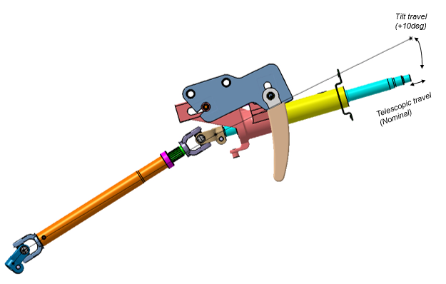
Steering column is the piece that attaches the steering wheel to the internal steering mechanism of the vehicle. The tilt steering mechanism allows selection of the steering wheel position (in the vertical direction) to match the driver’s driving posture. This type of steering allows the driver to tilt the steering wheel for ease during entry and exit. This can be done by releasing a lever on the side of the steering column and moving the wheel into the desired position, where it locks itself in place.

conventional steering column: The main disadvantage of having a conventional steering column is that, the steering wheel’s height and angle cannot be adjusted as per the Driver's need.
Tilt steering wheel
To change the steering wheel angle, pull up the lock release lever A, tilt the steering wheel to the desired angle and release the lever.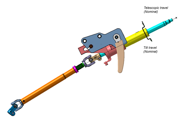


The Next advancement in Adjustable Steering Column is Tilt and Telescopic Steering Column, which offers the driver to tilt the steering wheel as well as retract and extend it according to needs. It is generally a tubular Steering column which slides up and down itself to contract and expand. There are two levers on the steering column assembly, out of which one controls the Tilt and other controls the Contraction and Expansion.


- It helped in driver ergonomics.
- Steering effort is distributed.
- Steering action can now be done at an angle thus driver can be sit comfortably.
Today, steering wheels and columns are power operated, with memory settings that move them out of the way for easier access, then return them to the pre-selected position automatically when we are ready to drive. Memory settings can be programmed for different drivers on some models. These are highly advanced compared to the adjustable steering wheel options of the classic car.

Electrically adjustable steering column manufactured by Lemförder Fahrwerktechnik. The electric motor 3 turns a ball nut via the gears 4 and this engages with the grooves 5 of the steering tube and shifts it (position 6) in the longitudinal direction (position 1). To change the height of the steering wheel (position 2), the same unit tips around the pivot 8 by means of the rod 7.
OCCUPANT SAFETY RESTRAINTS SYSTEM
- SEAT BELT with Pre-tensioners
- AIRBAGS
A seatbelt helps to prevent injury in the event of a car crash by reducing the velocity of a body as it experiences a sudden decrease in speed. Due to the body's inertia, which is its 'resistance to a change in speed or direction of travel', a passenger in a vehicle will want to continue travelling forwards once the car has reached a sudden stop.
If the vehicle is travelling at 50mph and crashes into a brick wall, instantly reducing its velocity to zero, the passenger will continue moving forwards at 50mph unless there is something in front of them to create a 'stopping force'. This is because the velocities of the car and passenger are independent.
A seatbelt spreads the stopping force needed to decelerate the passenger across their body. This prevents the body from hitting the windshield or steering column of a car at high speed, which could easily result in injury or death.
The belt is designed to apply most of the stopping force required to the pelvis and rib cage, both of which are relatively robust. Since stress is inversely proportional to the area at which a force is being applied, we can deduce that if the stopping force is spread across a larger area, the less stress the body will experience in the event of a crash.
Due to the fact that an abrupt stopping force could contribute to a passenger's injury, the material of which a seatbelt webbing is constructed from polyester or nylon is to allow for a small amount of movement as the body tries to move forwards. Lengthening the time taken for the body to come to a stop helps to reduce the impact that the body experiences.
This is the most commonly used seat belt system for passenger cars worldwide.


Retractor mechanism:
This is the most commonly used mechanism in seat belts. The retractor mechanism uses a spool as its central element. The spool is attached to one end of the webbing. A spring is available inside the retractor that provides a rotational force.
This is the most commonly used mechanism in seat belts. The retractor mechanism uses a spool as its central element. The spool is attached to one end of the webbing. A spring is available inside the retractor that provides a rotational force.

When the webbing is pulled
out, the spool rotates counter-clockwise, which turns the
attached spring in the same direction. Effectively, the rotating spool
works to untwist the spring. The spring wants to return to its original
shape, so it resists this twisting motion. If the webbing is released,
the spring will tighten up, rotating the spool clockwise until there is
no more slack in the belt.
The retractor has a locking mechanism that stops the spool from rotating when the car is involved in a collision. There are two types of locking systems is being used:
- systems triggered by the car's movement
- systems triggered by the belt's movement
systems triggered by the car's movement

The central operating element in this mechanism is a weighted pendulum. When the car comes to a sudden stop, the inertia causes the pendulum to swing forward. The pawl on the other end of the pendulum catches hold of a toothed ratchet gear attached to the spool. With the pawl gripping one of its teeth, the gear can't rotate counter-clockwise, and neither can the connected spool. When the webbing loosens again after the crash, the gear rotates clockwise and the pawl disengages.
systems triggered by the belt's movement

This system locks the spool when something jerks the belt webbing. The activating force in most designs is the speed of the spool rotation.
The central operating element in this design is a centrifugal clutch -- a weighted pivoting lever mounted to the rotating spool. When the spool spins slowly, the lever doesn't pivot at all. A spring keeps it in position. But when something yanks the webbing, spinning the spool more quickly, centrifugal force drives the weighted end of the lever outward.
The extended lever pushes a cam piece mounted to the retractor housing. The cam is connected to a pivoting pawl by a sliding pin. As the cam shifts to the left, the pin moves along a groove in the pawl. This pulls the pawl into the spinning ratchet gear attached to the spool. The pawl locks into the gear's teeth, preventing counter-clockwise rotation.
The extended lever pushes a cam piece mounted to the retractor housing. The cam is connected to a pivoting pawl by a sliding pin. As the cam shifts to the left, the pin moves along a groove in the pawl. This pulls the pawl into the spinning ratchet gear attached to the spool. The pawl locks into the gear's teeth, preventing counter-clockwise rotation.
In some newer seatbelt systems, a pretensioner also works to tighten the belt webbing.
The locking mechanism nowadays uses two sensors to lock the spool. The first is the vehicle deceleration sensor that detects any sudden deceleration in the vehicle and the second is the webbing sensor to detect any violent pull outs of the webbing.
Pre-tensioners:
A conventional seat belt locking mechanism will only lock the rotation of the spool. A pre-tensioner will actually pull the belt in once the car comes to an abrupt stop. Therefore, it helps move the occupants in the opposite direction of the momentum that tends to carry them forward.
A conventional seat belt locking mechanism will only lock the rotation of the spool. A pre-tensioner will actually pull the belt in once the car comes to an abrupt stop. Therefore, it helps move the occupants in the opposite direction of the momentum that tends to carry them forward.
Generally, pre-tensioners are wired to the same central control processor that activates the car's air bags. The processor monitors mechanical or electronic motion sensors that respond to the sudden deceleration of an impact. When an impact is detected, the processor activates the pre-tensioner and then the air bag.


The central element in this pretensioner is a chamber of combustible gas. Inside the chamber, there is a smaller chamber with explosive igniter material. This smaller chamber is outfitted with two electrodes, which are wired to the central processor.
When the processor detects a collision, it immediately applies an electrical current across the electrodes. The spark from the electrodes ignites the igniter material, which combusts to ignite the gas in the chamber. The burning gas generates a great deal of outward pressure. The pressure pushes on a piston resting in the chamber, driving it upward at high speed.
When the processor detects a collision, it immediately applies an electrical current across the electrodes. The spark from the electrodes ignites the igniter material, which combusts to ignite the gas in the chamber. The burning gas generates a great deal of outward pressure. The pressure pushes on a piston resting in the chamber, driving it upward at high speed.


Load limiter:
In very violent crashes, seat belts can incur serious damages on the occupants, especially the old people who cannot take much load on their rib cages. The harder the impact of collision, the harder will be the force of the seat belt to stop the occupant.
The basic idea of introducing a load limiter is to limit the force of the pre-tensioner on the occupants. Load limiter allows the belt or webbing to extend a bit more when a great deal of impact is applied on it. The best way to achieve this is by integrating a torsion bar with the retractor mechanism. The torsion bar is attached to the locking mechanism on one end and the spool on the other end.
The basic idea of introducing a load limiter is to limit the force of the pre-tensioner on the occupants. Load limiter allows the belt or webbing to extend a bit more when a great deal of impact is applied on it. The best way to achieve this is by integrating a torsion bar with the retractor mechanism. The torsion bar is attached to the locking mechanism on one end and the spool on the other end.

Seat belts work in combination with the airbags and hence it is necessary that the airbags deploy in order to save the occupant from injuries.
Airbags:

An airbag is more correctly known as a supplementary restraint system (SRS) or supplementary inflatable restraint (SIR). The word "supplementary" here means that the airbag is designed to help the seat belts protect the occupants rather than replace them (relying on an airbag to protect the occupants without fastening the seatbelt is extremely dangerous). The goal of an airbag is to slow the passenger's forward motion as evenly as possible in a fraction of a second.
It was invented by John W. Hetrick of Newport, Pennsylvania,1952, who came up with the idea after an accident in which he swerved his car off the road into a ditch to avoid hitting a rock, almost throwing his daughter through the windshield. From 1987 to 2015, frontal air bags saved 44,869 lives.
The Air Bag typically consists of the following 3 parts:
1. The Bag itself is made of a thin, nylon fabric, which is folded into the steering wheel or dashboard or, more recently, the seat or door.
2. The SENSOR is the device that tells the bag to inflate. Inflation happens when there is a collision force equal to running into a brick wall at 10 to 15 miles per hour (16 to 24 km per hour).
Two types of airbag sensors used in cars are electrical and mechanical. Electrical sensors vary in design.
Mechanical actuators
Inside the air bag assembly is a single mechanical impact sensor that trips a firing pin when a severe enough jolt is experienced. The firing pin ignites a primer which sets off the sodium azide pellets to inflate the bag.
Electromechanical actuators
Electromechanical "ball and tube" mechanism, which basically consists of a small tube containing a circuit switch and ball that's held together by a small magnet. If a collision occurs, the ball is dislodged from the magnet and rolls forward in the tube, hitting a switch that completes the electrical circuit.


Electronic sensors use a tiny accelerometer that has been etched on a silicon chip (that measures acceleration or force) detects the change of speed.
Mechanical sensors work independent of the electrical system and respond similarly to the electrical sensors, Since a mechanical sensor does not require a power source, it cannot be deactivated like an electrical sensor can when the battery is disconnected.

3. The AIR BAG'S INFLATION SYSTEM

If the deceleration is great enough, the accelerometer triggers the airbag circuit (Normal braking doesn't generate enough force to do this). The airbag circuit passes an electric current through a heating element(igniter). Inside the airbag is a gas generator containing a mixture of NaN3, KNO3, and SiO2. When the car undergoes a head-on collision, a series of three chemical reactions inside the gas generator produce gas (N2) to fill the airbag and convert NaN3, which is highly toxic to harmless glass.

The signal from the deceleration sensor ignites the gas-generator mixture by an electrical impulse, creating the high-temperature condition( 240–365°C) necessary for NaN3 to decompose. The nitrogen gas that is generated then fills the airbag. The bag then literally bursts from its storage site at up to 200 mph (322 kph). The purpose of the KNO3 and SiO2 is to remove the sodium metal (which is highly reactive and potentially explosive) by converting it to a harmless material.
2 NaN3 --> 2 Na(solid) + 3 N2 (gas)
 |
| 0.03 SECOND is all it takes to inflate an air bag |
 |
| inflation stages of 0ms,10ms,20ms,30ms |
First, the sodium reacts with potassium nitrate (KNO3) to produce potassium oxide (K2O), sodium oxide (Na2O), and additional N2 gas. The N2 generated in this second reaction also fills the airbag, and the metal oxides react with silicon dioxide (SiO2) in a final reaction to produce silicate glass, which is harmless and stable. (First-period metal oxides, such as Na2O and K2O, are highly reactive, so it would be unsafe to allow them to be the end product of the airbag detonation.) The airbag in passenger side container usually holds 200 grams of sodium azide, while the one on driver-side contains just 50 grams based on the size of airbag.

Immediately after inflation, when the chemical burn is complete, the airbag begins to deflate as the gasses escape from holes in the fabric, so the occupant can move.
There are two types of airbags;
- Frontal airbags.
- Side-impact airbags.
- Seat-mounted
- Curtain
- Tubular
- Door-mounted
- Combo


Rear-end collisions

Rear-end accidents occur when the front end of one vehicle hits the rear end of another one. Motorists are required to maintain a safe distance from the vehicle in front of them so they can slow down and stop when necessary—even in an emergency situation or poor driving conditions. According to the National Highway Traffic Safety Administration (NHTSA), an estimated 40 percent of all car accidents are rear-end collisions.
Tailgating. When a driver is tailgating, not maintaining a safe distance from other vehicles. In addition, tailgating makes it impossible to stop in an emergency situation when the vehicle in front must quickly slow down or slam on his brakes.
Distracted driving. It only takes a few seconds of distracted driving where the driver’s mind and eyes are not on the driving to miss a vehicle slowing down or braking. Eating and drinking, reading a GPS, texting, talking on a cell phone, and looking at instrument panels are some of the common distractions that cause a driver to rear-end another vehicle.
Intoxication. When a driver is intoxicated due to drug use or alcohol consumption, his reaction time is slowed and his general driving abilities impaired. This could result in him not judging the time he needs to stop, failing to see the motorist in front of him brake, or engaging in other unsafe driving practice that cause a rear-end wreck.
Weather conditions. Rain, ice, snow, and fog can reduce visibility and make driving treacherous. When a motorist is not more careful, he can easily slide into the back end of another vehicle if he loses control or is unable to stop.
Fatigue. Inattention is the consequence when a driver drives when he is drowsy. He may misjudge distances or not see the need to stop because his eyes are closed for a few seconds or longer if he falls asleep.
Speeding. As with tailgating, a speeding driver does not leave enough space between his vehicle and the one in front of him.
Road conditions. Road conditions, such as potholes, hidden or bent signs, or malfunctioning traffic lights can all be contributing factors in rear-end collisions.
Frontal object detection:
This task is solved by processing raw data of a radar, Lidar and a camera to detect and track moving and non-moving objects. Sensors are designed to provide specific data extracted from the environment. For example, lidar provides features like position and shape (lines) of obstacles within its field of view, camera sensors provide visual features that can be used to infer appearance information from obstacles, like class(colors, textures or shapes) of the objects.

- Raw data of radar and camera are processed to detect moving objects. These processings are done in two steps: first of all, each sensor delivers informations about moving objects that it has detected. In a second step, and secondly these informations are used to detect moving pedestrians and moving vehicles. Radar output is used for gating purposes to confirm the detections at each stage and assign a good range and velocity to the detected object. The camera output is then used to confirm the initial detection and refine the object lateral position.
- The Fusion processing which takes as an input the list of the detected objects (pedestrians and vehicles) provided by both kind of sensors and delivers a fused list of
detected objects.
- The Tracking processing module which takes as an input the fused list of objects and delivers a list of tracked objects. Raw lidar scans and vehicle state information are processed to recognize static and moving objects, which will be maintained for tracking purposes.
 |
| (a) detection level, (b) tracking level |


Rear object detection systems monitor a specific area behind a vehicle, detect objects, and provide warnings to drivers when they are approaching an object behind the vehicle while in reverse. These systems assist the driver in avoiding collisions during backing or parking maneuvers. Rear object detection systems can be integrated with other sensors, such as side object detection sensors to cover other blind spot areas around a vehicle.
Radar technology is also used for rear object detection systems. Radar typically operates in the ultra-high-frequency or microwave range of the radio-frequency spectrum. These radio frequency waves are transmitted from the vehicle at defined intervals within a specific coverage area. The sensor collects echoes from electromagnetic waves that bounce off
objects behind the vehicle. These echoes are sent to a signal processing unit and communicated to a driver interface. Some processing units utilize algorithms for object detection, object tracking, and angle measurement to provide specific distance information.
objects behind the vehicle. These echoes are sent to a signal processing unit and communicated to a driver interface. Some processing units utilize algorithms for object detection, object tracking, and angle measurement to provide specific distance information.
Camera Systems: Bendix also offers an integrated side and rear camera system that uses video type cameras to assist drivers in detecting objects in those areas that are sometimes not visible using mirrors alone. The images are projected into the same display unit where drivers view images from the cameras.
The driver interface consists of a graphical or digital visual display that shows the distance from the vehicle to a specific object. Other visual alerts consists of a series of lights which change color or light up as objects are detected. These visual alerts can be used in combination with audible alerts that vary in tone and frequency as the vehicle moves closer to an object.
Applications
Rear object detection systems provide an added measure of safety during backing and parking maneuvers. Many collisions that occur while backing and parking are caused when the driver cannot see what is behind the vehicle. If objects come into the path of the vehicle after the driver has checked mirrors and begun the backing and/or parking maneuver, then the driver may not be aware of the potential hazard. These systems can provide an advance warning so that the driver has additional time to stop and avoid a collision with objects behind his vehicle.
Object detection with braking interactions:
This system includes an object detector, a host vehicle speed sensor, brake modulator and a control unit configured to be electronically connected to at least the object detector and the host vehicle speed sensor for automatically controlling.
Depending on a host vehicle speed and a relative distance, a braking force needed for an automatic braking operation, containing preliminary braking control and supplementary braking control, without driver's braking action when a host vehicle is approaching a frontally positioned object.
The control unit detects the presence or absence of a driver's intention for lane-changing. In the presence of the driver's intention for lane-changing, the preliminary braking control initiated prior to the driver's braking action is inhibited or the degree of limitation on the supplementary braking control, through which a value of a controlled quantity is brought closer to a target deceleration rate needed for collision-avoidance, is reduced.

A collision avoidance system, also known as a pre-crash system, forward collision warning system, or collision mitigating system
is an advanced safety technology that monitors a vehicle’s speed, the
speed of the vehicle in front of it, and the distance between the
vehicles. If vehicles get too close due to the speed of the rear
vehicle, the FCW system will warn that driver of an impending crash. According to Insurance Institute for Highway Safety, collision warning system can reduce accidents by 27%.
Once
an impending collision is detected, these systems provide a warning to
the driver. When the collision becomes imminent, they take action
autonomously without any driver input (by braking or steering or both).
Collision avoidance by braking is appropriate at low vehicle speeds
(e.g. below 50 km/h (31 mph)), while collision avoidance by steering may
be more appropriate at higher vehicle speeds if lanes are clear. Cars
with collision avoidance may also be equipped with adaptive cruise
control, using the same forward-looking sensors.
It will significantly reduce the chance of a crash or a fatal accident. GPS sensors can detect fixed dangers such as approaching stop signs through a location database.


Bumper/frontal design for safety
The front and rear of the vehicle should be protected in such a manner that low-speed collisions will only damage the vehicle slightly, or not at all. Prescribed bumper evaluation tests (US Part 581, Canada CMVSS 215, and ECE-R 42) specify minimum requirements in terms of energy absorption and installed bumper height. Bumper evaluation tests in accordance with US Part 581 (4 km/h barrier collision, 4 km/h pendulum tests) must be passed by a bumper system whose energy absorber is of the no-damage absorber type. The requirements of the ECE standard are satisfied by plastically deformable retaining elements located between the bumper and the vehicle body structure. In addition to sheet steel, many bumpers are manufactured using fiber-reinforced plastics and aluminum sections.

Collision avoidance system:
The
Forward Collision Warning (FCW) system uses a radar to detect vehicles
or obstacles in front of the car. The system calculates the distance to
the object in front and, if the car gets close enough that there is a
risk of collision, sounds an alarm and displays a visual alert,
prompting the driver to apply the brakes. It’s important to note that FCW systems do not take full control of the vehicle or keep the driver from operating it.
It will significantly reduce the chance of a crash or a fatal accident. GPS sensors can detect fixed dangers such as approaching stop signs through a location database.
Radar or Lidar Monitoring
The
radar unit sends out waves that bounce off of surfaces (cars, trucks,
bicycles, pedestrians, etc.) and return back to the vehicle’s
forward-mounted sensor.
As
fast as these radio waves are, they still take a little bit of time to
travel from one place to another, so the collision avoidance system can
use the time it takes for the waves to bounce back to calculate
distance—in this case, the distance from the car to whatever is in front
of it.
On some systems, radar pings are sent 20 times per second, allowing it to warn of split-second changes in traffic.
Bumper/frontal design for safety
The front and rear of the vehicle should be protected in such a manner that low-speed collisions will only damage the vehicle slightly, or not at all. Prescribed bumper evaluation tests (US Part 581, Canada CMVSS 215, and ECE-R 42) specify minimum requirements in terms of energy absorption and installed bumper height. Bumper evaluation tests in accordance with US Part 581 (4 km/h barrier collision, 4 km/h pendulum tests) must be passed by a bumper system whose energy absorber is of the no-damage absorber type. The requirements of the ECE standard are satisfied by plastically deformable retaining elements located between the bumper and the vehicle body structure. In addition to sheet steel, many bumpers are manufactured using fiber-reinforced plastics and aluminum sections.
No comments:
Post a Comment