Heating, Ventilation and Air conditioning
HVAC is the technology of indoor and vehicular environmental comfort. Its goal is to provide thermal comfort and acceptable indoor air quality depending on the inputs of the operator as well as electronic sensors. It is the process of "exchanging" or replacing air in any space to provide high air quality which involves temperature control, oxygen replenishment, and removal of moisture, odors, smoke, heat, dust, airborne bacteria, and carbon dioxide. Ventilation removes unpleasant smells and excessive moisture, introduces outside air, keeps interior building air circulating, and prevents stagnation of the interior air.
Components of a Basic HVAC System
1. Cabin Air Filter

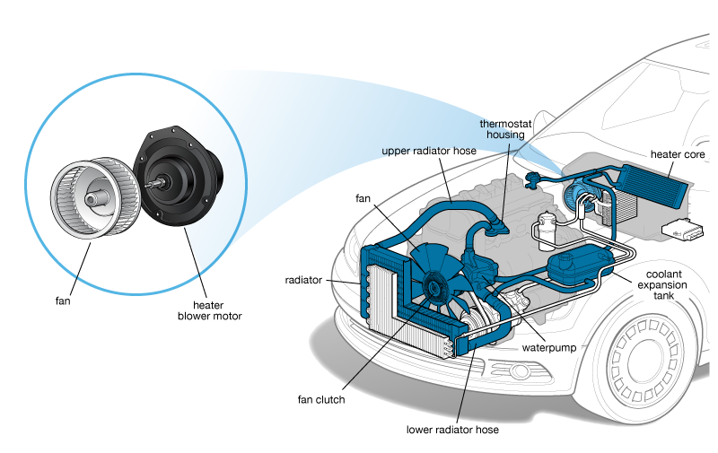
2. Heater Blower/Blower Motor

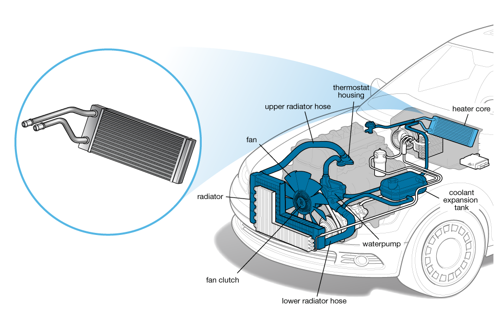
3. Heater Core

Heater shutoff valve
The heater shutoff valve blocks the flow of coolant through the heater core when the A/C system is set to A/C max or the temperature control is set to it’s coldest position.


4. Evaporator Core

The air-conditioning evaporator is a small radiator inside the dashboard that provides cold air for the air-conditioning system. It’s called the evaporator because it’s where the freezing liquid refrigerant takes on any heat from the air blown through it and changes into a gaseous state (evaporating it) before returning it to the air-conditioning condenser to shed the heat; the process is constantly repeated. The air that emerges from the air conditioner is cold as a result.
5. Evaporator Drain

6. Mode Doors


 |
| a) flow through upper vents b) floor vents c) flow through defogger vents |
7. Blend Door

The blend door is not much different than the mode doors except it controls how much air passes through the heater core. The more air that passes through the heater core, the warmer the air will be at the vents. A blend door moves to vary the amount of air passing through the vehicle’s heater core. The blend door is controlled by a blend door actuator, which can be a cable or an electric motor.
Controlling the Doors
1. Cable Style
Cable style is by far the most simple as well as the most reliable system. They are usually found on older base model vehicles but some newer midrange manufacturers still use this system for its reliability. Cables are attached to the heater control knobs, which open and close the mode and blend doors to achieve the air flow desired. The blower motor, A/C compressor engagement and recirculation flap may still be electronically controlled. Cable systems are generally the most reliable but they are not the most convenient. These systems usually do not have any sensors other than the sensors normally found in all A/C systems.

2. Vacuum Actuated


Vacuum actuated systems use engine vacuum to open and close the blend, mode and recirculate doors. A vacuum hose from the engine intake manifold comes through the firewall and into the cabin. Engine vacuum is redirected to the appropriate actuator to control the doors and airflow, based on the operators request. This system may still requires to make corrections to the air temperature or it may have an auto feature that will maintain a set cabin temperature. It may still need to be turned the A/C on or off manually. One of the serious downsides to this system is the complex vacuum routing under the dash. Over time the vacuum lines can leak and cause poor idle or other drive-ability problems because now the engine is pulling in unmetered air. It can be tricky to find these leaks.
Stepper Motor
These systems are fully electronic, and almost always have a automatic temperature regulating feature. Simply put, a stepper motor is an electronically controlled motor that can move to a fine tuned degree of rotation and hold. They use a series of sensors to decide at what temperature, and how hard to blow the air into the cabin. These systems usually use a PWM (pulse width modulation) variable speed heater blower to better control air flow. The mode doors can still be left up to the operator even in auto mode. The electronic stepper motors may be attached to the doors themselves or be connected by a cable or lever. One problem with this system in the past was the placement of the cabin air temperature sensor. If the sensor is near the drink holder, the system would supply full cold in the middle of winter or the system would supply with as much heat as it can give. This is no longer a problem on modern systems, modern systems use multiple cabin air temperature sensors and place them away from anything that may skew readings.
These systems are fully electronic, and almost always have a automatic temperature regulating feature. Simply put, a stepper motor is an electronically controlled motor that can move to a fine tuned degree of rotation and hold. They use a series of sensors to decide at what temperature, and how hard to blow the air into the cabin. These systems usually use a PWM (pulse width modulation) variable speed heater blower to better control air flow. The mode doors can still be left up to the operator even in auto mode. The electronic stepper motors may be attached to the doors themselves or be connected by a cable or lever. One problem with this system in the past was the placement of the cabin air temperature sensor. If the sensor is near the drink holder, the system would supply full cold in the middle of winter or the system would supply with as much heat as it can give. This is no longer a problem on modern systems, modern systems use multiple cabin air temperature sensors and place them away from anything that may skew readings.
Working
The re-circulation flap, it determines whether air for the HVAC system is taken from outside the cabin or recirculated air from the cabin. Outside air has to pass through a cabin air filter before making its way into the rest of the HVAC system. Outside air is usually taken from under the wiper cowl.
Next is the blower motor, this determines how hard to blow air into the cabin. After that air passes through the A/C evaporator. The evaporator core does not absorb heat/cool the air unless the compressor is activated, therefore the evaporator does not need to be bypassed when the A/C is not in use. From there the air comes to the blend door.

Possible Settings
1. Full Heat

In this setting the operator has demanded full heat. 100% of air flow is directed through the heater core by the blend door to deliver the most heat possible to the main upper vents.
In this setting the operator has selected full cold but has left the A/C off by either selecting economy mode or by not selecting A/C on. 100% of the air flow is directed around the heater core to allow filtered air at ambient temperature to enter the cabin through the main upper vents.
2. Max A/C

In this setting the operator has selected max A/C. The A/C compressor engages and the evaporator begins to absorb heat. To get the most cooling power, the HVAC system takes air from the cabin that has already been cooled once and cools it again instead of trying to cool hot ambient air.
3. Economy Mode
In this setting the operator has selected full cold but has left the A/C off by either selecting economy mode or by not selecting A/C on. 100% of the air flow is directed around the heater core to allow filtered air at ambient temperature to enter the cabin through the main upper vents. In some cases A/C is not required to provide adequate cooling. Without the A/C compressor running the vehicle will get noticeably better fuel economy.

Air Conditioning System
Air conditioning systems are first appeared in luxury automobiles in the early 1940’s. Vehicle’s air conditioning system does not create cold air like. In reality, it helps to remove the heat and humidity from inside the passenger compartment of the vehicle, leaving behind cooler air. There are four basic functions an air conditioning system involves- temperature control, air circulation control, and humidity control and air purification. An air conditioner uses the refrigerant absorbing heat as it evaporates. The air conditioning system goes by four principles to fulfill it. Air conditioning's main principles are Evaporation and Condensation, then Compression and Expansion.
Compression: The compressor is the work horse of the air conditioning system, powered by a drive belt connected to the crankshaft of the engine. When the aircon system is turned on, the compressor pumps refrigerant vapour under high pressure to the condenser.
Condensation: The condenser is a device used to change the high-pressure refrigerant vapor to a liquid. It is mounted in front of the engine's radiator, and it looks very similar to a radiator. The vapour is condensed to a liquid because of the high pressure that is driving it in, and this generates a great deal of heat. The heat is then in turn removed from the condenser by air flowing through the condenser on the outside.
Receiver: The now liquid refrigerant moves to the receiver-dryer. This is a small reservoir vessel for the liquid refrigerant, and removes any moisture that may have leaked into the refrigerant. Moisture in the system causes havoc, with ice crystals causing blockages and mechanical damage.
Expansion: The pressurised refrigerant flows from the receiver-drier to the expansion valve. The valve removes pressure from the liquid refrigerant so that it can expand and become refrigerant vapour in the evaporator.
Evaporation: The evaporator is another device that looks similar to a car radiator. It has tubes and fins and is usually mounted inside the passenger compartment behind the fascia above the footwell. As the cold low-pressure refrigerant is passed into the evaporator, it vaporises and absorbs heat from the air in the passenger compartment. The blower fan inside the passenger compartment pushes air over the outside of the evaporator, so cold air is circulated inside the car. On the 'air-side' of the evaporator, the moisture in the air is reduced, and the 'condensate' is collected and drained away.
Compressor: The compressor then draws in the low-pressure refrigerant vapour to start another refrigeration cycle. The refrigeration cycle then runs continuously, and is regulated by the setting of the expansion valve.
The fluid that passes around the whole system is the refrigerant. The refrigerant can evaporate at a low temperature, and then condense again at a higher pressure. In the bad old days, R-12 was the refrigerant used in almost all cars. It was widely available, however it was found to be a contributor to the hole in the earth's ozone layer as it was a chlorofluorocarbon (CFC). These refrigerants were discontinued, and all cars after 1996 use a non-CFC fluid called R-134A which is kinder to the environment.

Unitary Air Conditioning System
- In unitary air conditioning system, the assembled air conditioner is installed in or adjacent to the space to be conditioned.
- Interior air is cooled as a fan blows it over the evaporator and the exterior air is heated as a fan blows it over the heater core.
- In this process, heat is supplied from the room and discharge to the environment.
- It is used when different zones in a car are to be air-conditioned.

Dual-zone automatic climate control is when two separate sections of the vehicle can maintain different preferred temperatures autonomously. Usually this means the driver and the front passenger can both choose a temperature that works for them. In some larger vehicles, this might mean that the front seats and the back seats both have independent automatic temperature controls for the heating and the air conditioning.

Cars with dual zone Acura RDX, Toyota Prius, Honda Odyssey, Hyundai Sonata
Air space diffusion

The objective of air space diffusion system is to evenly distribute conditioned & outdoor air to provide healthy & comfortable indoor environment,or appropriate environment inside the vehicle cabin. It comprises air vents for diffusing air-conditioning air or external affair these air vents comprising flaps which are orientable so as to get the orientation of the airflow they deliver.
Outside Rear View Mirror(ORVM)
A wing mirror, also known as the fender mirror, door mirror, outside rear-view mirror or side view mirror, is a mirror found on the exterior of motor vehicles for the purposes of helping the driver to see areas behind and to the sides of the vehicle, outside the driver's peripheral vision (in the 'blind spot').


Classification:
- Internally Adjustable
- Manual
- Electrical
- Externally adjustable
- Manual
Internally adjustable
Internally
adjustable ORVM means there can be a manual handle/joystick near the
window by which the mirror position can be adjusted (without moving
hands outside and physically adjusting).
Manual Electronic Outside Rear View Mirror.
A conventional power mirror switch is essentially two rocker switches
built into a single housing. Each rocker switch is connected to two
wires that are connected to a reversible DC (direct current) motor
inside the side view mirror on either door. Each rear view mirror has
two DC motors. One DC motor operates the up/down function while the
other DC motor operates the left/right function.

Both
of the rocker switches inside the power mirror switch are constantly
connected to the vehicle’s electrical ground circuit with the switch at
rest. When the switch is pressed, the switch in any mirror direction,
the switch connects one of the two wires of a motor to power (12 volts
DC) while keeping the other circuit connected to ground. Electricity
then flows through the switch to the DC motor and the mirror head moves
in the intended direction. If the same switch is pressed to the opposite
direction, the electricity is reversed to the mirror motor and the
mirror moves in the opposite direction.


Memory Function : The mirrors work in conjunction with the adjustment of seats. Different drivers have different driving adjustments with the seating and hence the seats are provided with memory function. Once the desired setting is pressed, the seats adjust automatically as per the drivers requirement, along with the exterior mirrors which are synchronized with the seat adjustment.
Automatic Tilt
: When the driver shifts the gear to reverse the side mirror
automatically tilts downward to give driver proper visibility of the
left hand side while reversing. The driver car have a view of the
roadside to rear left wheel to park the car conveniently in tight
parking situations. when the car is locked, the mirrors get retracted
automatically to save itself from any mishap by other vehicle when
parked and open it when the engine is turned on.
Central locking system
Central
locking system (also known as electric door locks or power locks)
allows the driver or front passenger to simultaneously lock or unlock
all the doors of an automobile or truck, by pressing a button or
flipping a switch.
Today, many cars with power door locks also have a radio frequency remote keyless system, which allows a person to press a button on a remote control key fob. It allows the windows to be opened or closed by pressing and holding a button on the remote control key fob, or by inserting the ignition key and holding it in the lock or unlock position in the external driver's door lock. The remote locking system confirms successful locking and unlocking through either a light or a horn signal.


Door
assembly consists of catch, pawl and latch. The door lock striker is
attached to the body pillar. Under closing operation the door lock
striker gets caught by the latch and hold in the closed position and
centres the door. The pawl positively locks the catch in position. This
lock condition is automatically aborted when opening procedures begin.
For this process the forces acting on inner or outer door handle are
transferred to the pawl and cause the catch release to open the door.
The door lock striker stays in the position while the catch swivels go
into an open position.
In a case of operation methods central locking system consists of two types of actuators: electromagnetic and pneumatic.
Electromagnetic
actuators rely on solenoids which lock or unlock doors using current
going in both directions (open/closed) through an electric module. On
this kind of system two types of arrangements are in use. First one uses
separate relays for each of action taken by the system. One dedicated
to open and another one to close the door. Both of them are controlled
by a transistor switching the circuit operated by the capacitor (storage
for energy necessary to operate system) which is releasing current
necessary to activate the locks. Another type uses two capacitors and
two relays working as a tandem. One pair is responsible for locking and
another for unlocking. When the circuit is closed a current is
discharged from the capacitor and the lock is either opened or closed.

Pneumatic actuators
are driven by a pneumatic central unit which controls vacuum/pressure
pump. When vacuum is applied actuators acting on mechanism lock or
unlock the door. The vacuum pump is driven by electric motor which is
working in both directions. Forward rotation creates a compressor action
(doors open), while backwards rotation creates vacuum (doors close).
Polarity on the electric motor is changed by a change-over control
switch.
In most modern cars electrical locking system replaced mechanical unit due to a demand for quality and reliability.


A
small electric motor turns a series of spur gears that serve as a gear
reduction. The last gear drives a rack-and-pinion gearset that is
connected to the actuator rod. The rack converts the rotational motion
of the motor into the linear motion needed to move the lock.

This
actuator can move the metal hook shown in this photo to the left or
right. When mounted in the car, it is vertical, so the hook can move up
or down. It mimics the motions when the knob is pulled up or pushed down.
 | ||
| worm and nut type |

while
the motor can turn the gears and move the latch, if the latch is moved
it will not turn the motor. This is accomplished by a neat centrifugal
clutch that is connected to the gear and engaged by the motor.

When
the motor spins the gear, the clutch swings out and locks the small
metal gear to the larger plastic gear, allowing the motor to drive the
door latch. If the the door latch is moved manually, all of the gears will turn except for the plastic gear with the clutch on it.

Automatic Garage Door Opening System
A
garage door opener is a motorized device that opens and closes garage
doors. Most are controlled by switches on the garage wall, as well as by
remote controls carried in the garage owner's cars, or more rarely, on
key chains.
The first garage door opener remote controls were simple and consisted of a simple transmitter (the remote) and receiver which controlled the opener mechanism. The transmitter would transmit on a designated frequency; the receiver would listen for the radio signal, then open or close the garage, depending on the door position.The disadvantage is that, they opened their neighbor’s garage door as well.
The second stage of the wireless garage door opener system consists of remote controls on these systems transmitted a digital code, and the receiver in the garage responded only to that code. The codes were typically set by eight to twelve DIP switches on the receiver and transmitter, so they allowed for 28 = 256 to 212 = 4,096 different codes. As long as neighbors used different codes, they would not open each other's garage doors. The intent of these systems was to avoid interference with nearby garage doors. The problem was that, the attacker would use a code grabber, which has a receiver that captures the remote's digital code and can re transmit that digital code at a later time. To rectify this, multicode systems were developed.
Tire pressure monitoring systems or Deflation Detection Systems:
A
tire pressure monitoring system (TPMS) is an electronic system designed
to monitor the air pressure inside the pneumatic tires on various types
of vehicles. TPMS report real-time tire-pressure information to the
driver of the vehicle, either via a gauge, a pictogram display, or a
simple low-pressure warning light.
TPMS can be divided into two different types.
1. Direct (DTPMS)
2. Indirect (ITPMS).
Rain Sensing Wiper System
Rain sensing wipers are the windscreen wipers which come into action automatically when they sense water on the windscreen of the vehicle.
Basic components

Rain
sensing wipers employ an electronic control module fitted near the
windscreen. It serves as the brain of this system. It uses optical
sensors to detect the moisture. The sensor is mounted in contact with
the inside of the windshield, near the rear view mirror.

2. Indirect (ITPMS).
Rain Sensing Wiper System
Rain sensing wipers are the windscreen wipers which come into action automatically when they sense water on the windscreen of the vehicle.
Basic components
- Rain sensor
- Microcontroller
- servo motor
Environment Information System
Environment Information System
is that a space sensors system using laser, ultrasonic or radar sensors
are installed in a highway environment and communication technology is
used to realize the information exchange between the Highway Information
server and vehicles, which provides vehicles with the surrounding road
information. Considering the high-speed feature of vehicles on highways,
when vehicles will be passing a road ahead that is prone to accidents,
the vehicle driving state should be predicted to ensure drivers have
road environment perception information in advance, thereby ensuring
vehicle driving safety and stability. In order to verify the accuracy
and feasibility of the Highway information server, a traditional
vehicle-mounted sensor system for environment perception is used to
obtain the relative driving state.

The
distributed sensors are placed on road sides and sense the environment
perception and send the information to sink sensor and then to the base
station. After obtained the information sent to system servers and
server evaluate the information and further disseminate the information
to the vehicles.
The system has four parts: the sensor nodes, base station, communication devices(connected with sink node) (laser, ultrasonic, radar, etc.) and wireless network and server systems.
Automotive lamps

Vehicle lighting systems are primarily safety devices, they provide visibility under night driving and convey vehicle state information to other drivers under all driving conditions. The vehicle forward lighting systems allow drivers to see the roadway, traffic control devices, route guidance signs, and targets in the roadway. The signaling and marking lamps and devices provide vehicle visibility and information on the motion characteristics of the vehicles to other drivers.
1. Exterior lamps and lighting devices
a. Roadway illuminating devices
- Headlamps—low and high beams
- Front fog lamps
- Auxiliary headlamps
- Cornering lamps
- Parking (front), tail, stop, and turn signal lamps
- Marking: side marker lamps, identification lamps (for trucks), and reflex
- reflectors
- Backup (reversing) lamps
- Daytime running lamps
- Rear fog lamps
- Under mirror flood lamps
- Cargo lamps (inside truck bed)
- Running board lamps (for trucks and SUVs)
a. Illuminated displays (graphics /labels) and controls
- Interior displays
- Lighted labels on controls
- Illumination lamps (or light-emitting diodes [LEDs]) for displays and controls
- Dome lights
- Map lights
- Courtesy/convenience lamps (e.g., lamps mounted under instrument panels to illuminate floor, lamps on doors or sun visors)
a. Engine, trunk, and cargo area lamps
b. Emergency, police, and service vehicle warning lamps (e.g., blue, yellow/amber, red, or white flashing or rotating warning lamps).

Stop lamps (brake lights)

Rear position lamps (tail lamps)

These are required to produce only red light and to be wired such that they are lit whenever the front position lamps are lit, including when the headlamps are on. Rear position lamps may be combined with the vehicle's stop lamps or separate from them. In combined-function installations, the lamps produce brighter red light for the stop lamp function and dimmer red light for the rear position lamp function. It produce minimum intensity ratios between the bright (stop) and dim (rear position) modes, so that a vehicle displaying rear position lamps will not be mistakenly interpreted as showing stop lamps, and vice versa.
Indicators


Turn signals—formally called "direction indicators" or "directional signals", and informally known as "directionals", "blinkers", "indicators" or "flashers"—are blinking lamps mounted near the left and right front and rear corners of a vehicle, and sometimes on the sides or on the side mirrors of a vehicle, activated by the driver on one side of the vehicle at a time to advertise intent to turn or change lanes towards that side.
Reversing (backup) lamps

This is to warn adjacent vehicle operators and pedestrians of a vehicle's rearward motion, and to provide illumination to the rear when backing up and each vehicle is equipped with one or two rear-mounted, rear-facing lamps. These are required to produce white light. The colour of the light emitted shall be white.
Reflex reflectors(Retroreflectors)
 A
retroreflector (sometimes called a retroflector or cataphote) is a
device or surface that reflects radiation (light, usually) back to its
source with a minimum of scattering. It is intended for pedestrians,
runners, motorized and non-motorized vehicles. It produces no light of
their own, but rather reflect incident light back towards its source,
for example, another driver's headlight.
A
retroreflector (sometimes called a retroflector or cataphote) is a
device or surface that reflects radiation (light, usually) back to its
source with a minimum of scattering. It is intended for pedestrians,
runners, motorized and non-motorized vehicles. It produces no light of
their own, but rather reflect incident light back towards its source,
for example, another driver's headlight.

Gas Discharge Lamps
 |
| Red rear side marker retroreflectors on Ford F-series trucks without direct illumination |
 |
| Red rear side marker retroreflectors on Ford F-series trucks with direct illumination |
Gas Discharge Lamps


An electric arc is the source of light in the gas discharge lamp, and the actual discharge bulb is only about 10 mm across. Two quartz glass electrodes protrude into the bulb. The gap between these electrodes is 4 mm, and the distance between the end of the electrode and the bulb contact surface is 25 mm.
At room temperature and under pressure the bulb contains a mixture of mercury, various metal salts and xenon. The xenon illuminates immediately after the light is switched on and evaporates the mercury and metal salts. The metal vapour mixture produces the high luminous efficiency. Most of the light is generated by the mercury and the colour spectrum is provided by the metal salts.
Ignition
A high voltage pulse causes a spark to jump across the electrodes, which ionizes the gap and creates a tubular discharge push.
Immediate light
The current flowing along the discharge path excites the xenon, which consequently emits light at about 20% of its continuous value.
Run-up
The lamp is now operated at increased wattage, and the temperature rises rapidly due to which the mercury and metal salts evaporate. The pressure in the lamp also increases with the increase of luminous flux. Consequently the light shifts from the blue to the white range.
LED

LEDs create light by electroluminescence in a semiconductor material. Electroluminescence is the phenomenon of a material emitting light when electric current or an electric field is passed through it - this happens when electrons are sent through the material and fill electron holes. An electron hole exists where an atom lacks electrons (negatively charged) and therefore has a positive charge. Semiconductor materials like germanium or silicon can be "doped" to create and control the number of electron holes. Doping is the adding of other elements to the semiconductor material to change its properties. By doping a semiconductor you can make two separate types of semiconductors in the same crystal. The boundary between the two types is called a p-n junction. The junction only allows current to pass through it one way, this is why they are used as diodes. LEDs are made using p-n junctions. As electrons pass through one crystal to the other they fill electron holes. They emit photons (light). This is also how the semiconductor laser works. The color of the light (corresponding to the energy of the photons) is determined by the energy required for electrons to cross the band gap of the semiconductor. White light is obtained by using multiple semiconductors or a layer of light-emitting phosphor on the semiconductor device.
The advantage of LED lights is that they light up instantly, are extremely efficient and last far longer than other light sources. Thus, they are frequently used in tail-lights and daytime running lights. However, with technology advancing, the problem of lower light intensity is being overcome to the point where LEDs are finding application in headlights. The additional benefit here is that LEDs can emit light that's far closer in colour to daylight. Of course, some manufacturers use LEDs for just low beams, while some have full (low and high beam) LED lights.The light itself is also much closer in tone to natural light, which makes driving at night less of a strain on the eyes.
Digital LED headlights
Using this system, we can drive with the headlights turned up high. The headlight is capable of shutting select areas of the light depending on the position of oncoming traffic. It is quite helpful as it prevents the car from blinding drivers ahead. This is expensive technology and has been introduced only on select luxury cars.

Adaptive headlights

Adaptive headlights are an active safety feature designed to make driving at night or in low-light conditions safer by increasing visibility around curves and over hills. When driving around a bend in the road, standard headlights continue to shine straight ahead, illuminating the side of the road and leaving the road ahead of the car in the dark. Adaptive headlights, on the other hand, turn their beams according to the steering input so that the vehicle’s actual path is lit up. Similarly, when a vehicle with standard headlights crests a hill, the headlight beams temporarily point upwards towards the sky. This makes it difficult for drivers to see the road ahead and for oncoming motorists to see the driver approaching. In contrast, adaptive headlights use a self-levelling system that points the light beam up or down, according to the position of the vehicle.
Adaptive headlight systems are made up of several sub components that are monitored and controlled by an electronic control unit (ECU). The sub components include:
- wheel speed sensors that monitor the speed of rotation of each wheel
- a yaw sensor that tracks a vehicle’s side-to-side movement, e.g., when turning a corner
- a steering input sensor that monitors the angle of the steering wheel and
- small motors attached to each headlight.
- Level Sensor– Sends the information about the vehicle’s position to the ECU
- Rain Sensor System- This sensor is fitted to the vehicle and the data is fetched via CAN network.
- ECU– This is the brain and considers all sensors information for generating the required illumination of lights.

Most adaptive headlight setups also include a self-levelling system. This system helps prevent headlights from pointing too far up or too far down when driving up or down hills. A self-levelling system includes a level sensor that sends information to the ECU about the vehicle’s position, specifically whether it is tilted forward or backwards. The headlights are then moved up or down to correct for the vehicle’s positioning. Some headlamps are integrated with Adaptive Highbeam Assist which eliminates the need to flip between high and low beams while also ensuring the path ahead is fully lit without ever straining the eyes of other drivers. As other cars approach, the headlamp range automatically adjusts based on the distance of oncoming traffic. The another feature of AHL is the adverse weather light which creates a wider dispersion of the light to improve visibility in rain, fog, or snow. This feature also reduces far-field illumination to minimise reflective glare affecting the driver’s own vehicle.
Cars with AHL:Ford S-Max, Nissan GT-R, Tesla- Model S, Hyundai Genesis, Subaru Outback..etc
Daylight Running Lamps

A daytime running lamp (DRL, also daytime running light) is an automotive lighting and bicycle lighting device on the front of a road-going motor vehicle or bicycle, automatically switched on when the vehicle is in drive, emitting white, yellow, or amber light. Their job isn't to help the driver see the road but to help other road users see the vehicle. Daylight running lamps for motor vehicles are now a legal requirement in Europe. They became mandatory for new cars manufactured from February 2011 and for commercial vehicles from August 2012.
In vehicles equipped with daytime running lights or DRLs, the system is automatic. They are intended to be on when the vehicle is driven without requiring any driver input. The way they work varies from automaker to automaker, and even from model to model. In nearly all the systems originally developed, they worked by using a lower power setting on already existing lights, typically the high beams.
LED-based lamps offer much higher energy efficiency than traditional incandescent bulbs. According to some estimates, the lower power consumption of LEDs for daylight running compared to conventional bulbs can result in a saving of two liters of petrol every 1000km in a conventional vehicle. They will also improve the effective range of plug-in hybrid and electric vehicles.
A further advantage of the LED-based option for daylight running is the much higher reliability of the components. The longevity of LEDs – they have an effective service life of more than ten years – means they may never need replacing during the lifetime of the vehicle. Furthermore, the smaller space required by LEDs compared to bulbs allows the daylight-running lamps to be placed in a wider variety of locations. LEDs for daylight running can react better to changes in driving conditions, increasing output when fog descends, for example, or reducing the brightness when the lamps can act as parking lights. As a result, effective dimming control over LED strings is a key requirement of power controllers.
A further advantage of the LED-based option for daylight running is the much higher reliability of the components. The longevity of LEDs – they have an effective service life of more than ten years – means they may never need replacing during the lifetime of the vehicle. Furthermore, the smaller space required by LEDs compared to bulbs allows the daylight-running lamps to be placed in a wider variety of locations. LEDs for daylight running can react better to changes in driving conditions, increasing output when fog descends, for example, or reducing the brightness when the lamps can act as parking lights. As a result, effective dimming control over LED strings is a key requirement of power controllers.
No comments:
Post a Comment